
Landfill and Soil Capping
On this page:
- Schematic
- Introduction
- Other Technology Names
- Description
- Development Status
- Applicability
- Cost
- Duration
- Implementability Considerations
- Resources
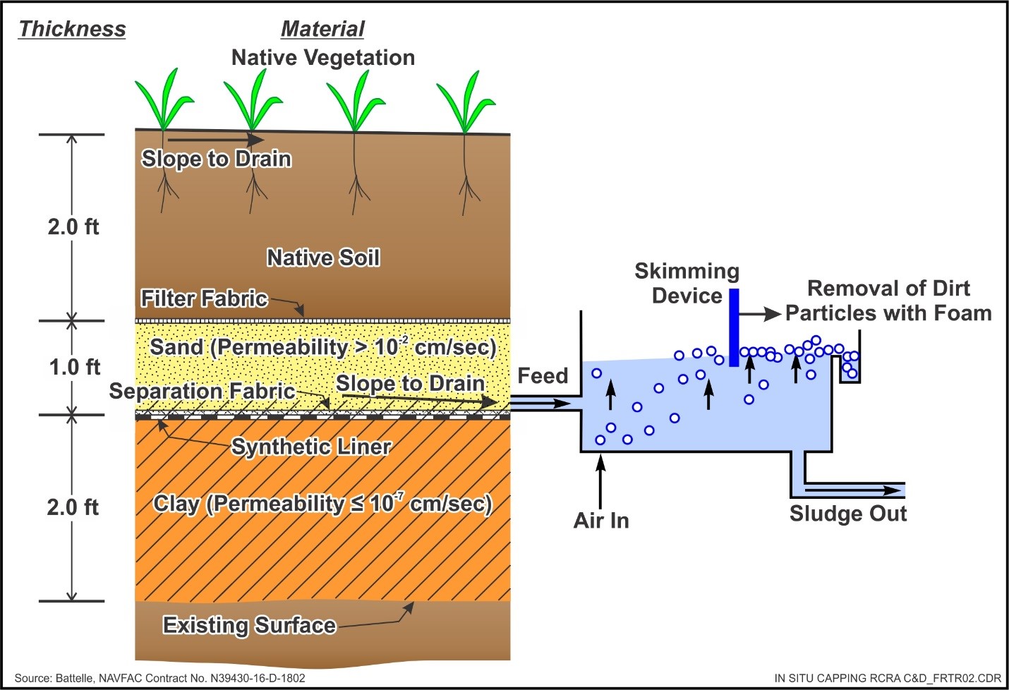
Schematic
This information may be reproduced without restriction as long as the source attribution is included.
Typical RCRA Subtitle C Cap Requirements
Introduction
Landfill and soil capping are containment technologies that form a barrier between a waste body or contamination source area and the ground surface, thereby minimizing the exposure of humans and environmental receptors to the contaminated media. The cap is typically designed to restrict surface water and rainwater infiltration into the subsurface waste body or contamination source area to reduce the potential for leaching of site contaminants.
Other Technology Names
Cap
Landfill Cover
Surface Cover
Description
Landfill and soil caps can be used to:
- Minimize exposure on the surface of a waste body or contaminant source zone.
- Prevent vertical infiltration of water into wastes that would create contaminated leachate.
- Contain waste while treatment is being applied.
- Control gas emissions from underlying waste.
- Prevent the occurrence of odors, disease vectors, and other nuisances.
- Create a land surface that can support vegetation and/or be used for other purposes.
The design of a cap is site specific and depends on many factors including: the nature of wastes being managed; local availability and costs of cap materials; the desired functions of the cap materials; the local climate, hydrogeology, and terrain; and the anticipated future use of the site. Caps can range from a one-layer system of vegetated soil to a complex multi-layer system of soils and geosynthetic materials depending on the type of waste. In general, less complex systems are required in dry climates and more complex systems are required in wet climates.
The most critical components of a landfill cap are the barrier layer that minimizes water infiltration and the drainage layer that transmits water across the cover. The barrier layer can be low-permeability soil (clay), geosynthetic clay liners (GCLs), or synthetic geomembrane liners. GCLs are factory-manufactured hydraulic barriers consisting of a layer of bentonite clay or other very low-permeability material supported by geotextiles and/or geomembranes, held together either mechanically or chemically. Synthetic geomembrane liners are factory manufactured using a variety of low permeability materials. GCLs and geomembranes are usually supplied in large rolls and are available in several thicknesses (20 to 140 thousandths of an inch [mil]), widths (15 to 100 feet), and lengths (180 to 840 feet) (EPA, 1993a).
The list of polymers used to make geosynthetic materials is extensive, but the common polymers used in cap liners include: polyvinyl chlorides (PVCs), polyethylenes of various densities, reinforced chlorosulfonated polyethylenes (CSPE-R), polypropylenes, and ethylene interpolymer alloys (EIA) (EPA, 1991a, 1993b). Soils used as barrier materials generally are clays that are compacted to a hydraulic conductivity no greater than 1 × 10⁻⁶ cm/sec. Compacted soil barriers are generally installed in 6-inch minimum lifts to achieve a thickness of 2 feet or more. A composite barrier uses both soil and a geomembrane, taking advantage of the properties of each. The geomembrane is essentially impermeable, but, if it develops a leak, the soil component prevents significant leakage into the underlying waste (EPA, 1993a). Table 1 summarizes key components of a conventional landfill cap.
The Resource Conservation and Recovery Act (RCRA) regulations contained in Title 40 of the Code of Federal Regulations (CFR) specify minimum design criteria for the establishment of caps for certain types of landfills. Subtitles C and D of RCRA provide criteria for hazardous waste treatment, storage, and disposal facilities and municipal solid waste landfills, respectively. The typical requirements for Subtitle C and D caps are listed in Table 2 below.
Table 1. Key Components of Conventional, Barrier-Type Landfill Covers
Layer |
Primary Function |
Typical Composition |
Cover Soil |
|
|
Drainage |
|
|
Barrier |
|
|
Gas Collection |
|
|
Foundation |
|
|
Table 2. Typical Requirements for RCRA Subtitle C and D Caps
Cap Element(a) |
Subtitle C Cap(b) |
Subtitle D Cap(b) |
Vegetative/ erosion control layer |
A 24-inch thick layer of earthen material |
A 6-inch thick layer of earthen material |
Drainage layer |
A 12-inch thick layer of sand |
Optional. See Subtitle C for materials of construction. Can also slope surface for run-off. |
Geosynthetic barrier |
Geosynthetic membrane or GCL |
N/A |
Geological material barrier |
A 24-inch thick layer of low- permeability compacted clay |
An 18- to 24-inch thick layer of compacted earthen material with permeability < 1x10⁻⁵ cm/sec |
Gas vent layer |
Necessary if methane will be generated due to the presence and degradation of organic compounds. Consists of a high permeability layer, which can either be a geonet composite membrane or a 12-inch thick layer of sand or pea gravel (c) |
Common for general refuse landfills that generate methane. See Subtitle C for gas collection materials of construction. |
Foundation Base Layer |
Installed immediately above the waste to provide stability and base for the other layers |
Installed immediately above the waste to provide stability and base for the other layers |
N/A — Not Applicable
- Cap elements are tabulated in order from the surface down.
- Final cover must be designed and constructed to have a permeability less than or equal to the bottom liner system or natural subsoils.
- Requirement for the gas vent layer depends on site-specific conditions.
Additionally, several alternative landfill cover (AFC) types have been proposed that differ in design and operational theory from the minimum recommended designs described in RCRA regulations (EPA, 1991b; ITRC, 2003a). AFC designs can be considered, but must be of equivalent performance to the specifications outlined above. These include, but are not limited to, asphalt, concrete, capillary barrier, and evapotranspiration (ET) covers (ITRC, 2003b).
Asphalt and concrete are not typically used for landfill barriers due to eventual deterioration from rainfall and freeze/thaw, but may be used for other surface cover applications to mitigate direct contact risk exposure pathways. A capillary barrier cover is a two-layer system composed of materials with distinct hydraulic properties to prevent water infiltration into the underlying soil by utilizing unsaturated soil mechanics principles. Capillary barriers use the contrast in unsaturated hydraulic properties between a fine- and coarse-grained material to store water. The finer soils of a capillary barrier hold infiltrating water by capillary forces and thus serve as a barrier to downward flow (ITRC, 2003b). ET covers, the most common of the alternatives, minimize downward migration of water into the waste body by storing infiltrating water within the cover system during cold/wet months and removing the water through ET processes during periods of growth and/or hot/dry months. ET covers perform best in arid and semi-arid environments such as those found in parts of the Great Plains and western states (EPA, 2011).
All covers should be designed to prevent the "bathtub" effect. The bathtub effect occurs when a more permeable cover is placed over a less permeable bottom liner or natural subsoil landfill then fills up like a bathtub.
Development Status and Availability
The following checklist provides a summary of the development and implementation status of the landfill capping technology:
☐ At the laboratory/bench scale and shows promise
☐ In pilot studies
☒ At full scale
☐ To remediate an entire site (source and plume)
☒ To remediate a source only
☐ As part of a technology train
☐ As the final remedy at multiple sites
☐ To successfully attain cleanup goals in multiple sites
Landfill capping systems are available through the following vendors:
☒ Commercially available nationwide
☐ Commercially available through limited vendors because of licensing or specialized equipment
☐ Research organizations and academia
Applicability
|
Contaminant Class Applicability Rating for Landfill and Soil Capping (Rating codes: Demonstrated Effectiveness, ◐ Limited Effectiveness, No Demonstrated Effectiveness, ♢ Level of Effectiveness dependent upon specific contaminant and its application/design, I/D Insufficient Data) | ||||||||
|---|---|---|---|---|---|---|---|---|
Nonhalogenated VOC |
Halogenated VOC |
Nonhalogenated SVOC |
Halogenated SVOC |
Fuels |
Inorganics |
Radionuclides |
Munitions |
Emerging Contaminants |
| ● | ● | ● | ● | ● | ● | ● | ● | I/D |
Landfill and soil capping may be used to contain in situ waste and can be applied to contain various types of chemicals of concern including halogenated and nonhalogenated volatile organic compounds (VOCs) and semi-volatile organic compounds (SVOCs), polychlorinated biphenyls (PCBs), ordnance compounds, inorganics, dioxins/furans, pesticides, and radioisotopes such as radium-226 (EPA, 1993a). Caps also may be applied to contaminant sources that are so large that other treatment is impractical. At mining sites for example, caps can be used to minimize the infiltration of water to contaminated tailings piles and to provide a suitable base for the establishment of vegetation. In conjunction with water diversion and detention structures, landfill caps may be designed to route surface water away from the waste area while minimizing erosion.
Cost
Landfill and soil caps are generally the least expensive way to manage the human health and ecological risks effectively. Rough-order-of-magnitude industry costs (in 2018 dollars) range between $300k/acre and $600k/acre (EPA, 1998a). Major cost drivers include:
Upfront Costs
- Nature of the contamination (e.g., hazardous versus non-hazardous waste)
- Areal extent of contamination requiring a cap
- Local climate, geomorphological and hydrogeological features of the site
- Proximity to cap materials (e.g., sands and clays)
- Drainage requirements
Operation and Maintenance Costs
- Inspection and maintenance (e.g., erosion repair, vegetation management)
- Long-term sampling and analysis requirements
- Vapor control and treatment
The list above highlights those cost dependencies generalized to landfill capping and does not consider the dependencies that are general to most in situ remediation technologies. Click here for a general discussion on costing which includes definitions and repetitive costs for remediation technologies. A project-specific cost estimate can be obtained using an integrated cost-estimating application such as RACER® or consulting with a subject matter expert.
Duration
Installation time for a typical RCRA cap often ranges from 1 to 4 months, depending on cap area, site conditions, and capping material. Long-term operation and maintenance is required to monitor cap integrity and leaks through the cap. The time period requiring active monitoring and maintenance is generally expected to be a minimum of 30 years (EPA, 2011).
The federal RCRA regulation specifies that leachate management must be performed for a minimum period of 30 years (EPA, 1989b), unless the regulatory agencies agree to a different timeframe. The duration of operation and maintenance is dependent on factors such as erosion, settling, or subsidence of the cap and is evaluated on a case-by-case basis.
Implementability Considerations
The following are key considerations associated with landfill capping:
- Caps may be temporary or final. Temporary caps can be installed before final closure of a site to minimize development of leachate until a better remedy is selected (EPA, 1993a). They are often used to minimize infiltration when the underlying waste mass is undergoing settling.
- Landfilling as a remediation technology does not lessen the toxicity, mobility, or volume of hazardous wastes, but does mitigate migration. Landfill caps then mitigate exposure to the landfill content and are most effective where most of the underlying waste is above the water table.
- A cap, by itself, cannot prevent the horizontal flow of groundwater through the waste, only the vertical entry of water into the waste. In many cases, landfill caps are used in conjunction with vertical containment walls to minimize horizontal flow and migration. Caps are not effective if groundwater is already or periodically in contact with the contaminated waste.
- Precautions must be taken to assume that the integrity of the cap is not compromised by land use activities (e.g., vehicular traffic). Specialized uses, such as siting solar photovoltaic systems on a landfill (EPA and NRML, 2013), may require additional considerations such as slope stability, differential settling, effects of anchoring systems and loading on integrity of the cap, leachate collection and gas collection systems, etc. that must be considered during the design, and operation and maintenance.
- In areas with high rates of subsidence and regions prone to earthquakes, the cap and its foundation should be designed appropriately (EPA, 1995). Changes in conditions, such as soil moisture, coastal erosion (e.g., Alaska North Slope), and earth movement, should be monitored as indicators of potential problems and mitigated before hazardous releases occur.
- Fluctuations in air temperature and precipitation may also affect the cap's integrity by causing cracking or erosion. In addition, plant roots and burrowing animals can undermine the cap's integrity.
- The effective life of landfill components (including cap) can be extended by long-term inspection and maintenance.
- Proper drainage design is critical to damage and penetration of the cover from excessive infiltration and ponding. Besides use of a drainage layer and surface sloping, the surface topography and size of the landfill may dictate use of other drainage design features such as side slope diversion channels, collection culverts, etc.
- Invasion by deep-rooted vegetation or burrowing animals can interfere with proper cap performance. Cobble biota barriers may be installed to ensure burrows do not impact liner or low permeability layers. Biota barrier will also double as a hydraulic break and drainage layer.
Resources
DOE. Technology Catalogue, Second Edition, Office of Environmental Management and Office of Technology Development, DOE/EM-0235 (1995) (PDF) (321 pp, 8.22 MB)
This document provides performance data on remedial investigation techniques and remediation technologies employed by the Department of Energy (DOE).
EPA. Geosynthetic Design Guidance for Hazardous Waste Landfill Cells and Surface Impoundments, Office of Research and Development, Cincinnati, OH, EPA/600/2-87/097 (1987) (PDF) (221 pp, 9.32 MB)
This document provides guidance on evaluation of geosynthetic materials used in hazardous waste land disposal cells and surface impoundments.
EPA. Technology Screening Guide for Treatment of CERCLA Soil and Sludge, Office of Solid Waste and Emergency Response, Washington, DC, EPA/540/2-88/004 (1988) (PDF) (136 pp, 3.96 MB)
This guide provides a screening methodology to identify feasible alternative treatment technologies for soils and sludges at Superfund sites.
EPA. Final Covers on Hazardous Waste Landfills and Surface Impoundments, Technical Guidance Document, Office of Solid Waste and Emergency Response, Washington, DC, EPA/530/SW-89/047 (1989) (PDF) (54 pp, 3.19 MB)
This document recommends and describes a design for landfill covers that will meet the requirements of RCRA regulations.
EPA. Compilation of Information on Alternative Barriers for Liner and Cover Systems, Office of Research and Development, Cincinnati, OH, EPA/600/2-91/002 (1990) (PDF) (93 pp, 4.07 MB)
This report contains a compilation of available information concerning alternative barrier materials and summarizes the issues identified in the associated EPA workshop.
EPA. Inspection Techniques for the Fabrication of Geomembrane Field Seams, Technical Guidance Document, EPA/530/SW-91/051 (1991a) (PDF) (190 pp, 7.75 MB)
This document provides guidance for construction quality control and construction quality assurance inspectors and related personnel as to the proper techniques for fabricating field seams in geomembranes.
EPA. Design and Construction of RCRA/CERCLA Final Covers, Seminar Publication, Office of Research and Development, Cincinnati, OH, EPA/625/4-91/025 (1991b)
This seminar publication provides regulatory and design personnel with an overview of design, construction, and evaluation requirements for cover systems for RCRA/CERCLA waste management facilities.
EPA. Engineering Bulletin Landfill Covers, Office of Research and Development, Cincinnati, OH, EPA/540/S-93/500 (1993a) (PDF) (8 pp, 819 KB)
This bulletin describes various aspects of landfill covers, their applicability, and limitations on their use and innovative techniques, site requirements, performance data, current status, and sources of further information regarding the technology.
EPA. Quality Assurance and Quality Control for Waste Containment Facilities, Technical Guidance Document, Office of Research and Development, RREL, Cincinnati, OH, EPA/600/R-93/182 (1993b) (PDF) (328 pp, 18.1 MB)
This document provides information needed to develop comprehensive quality assurance plans and to carry out quality control procedures at waste containment sites.
EPA. RCRA Subtitle D (258) Seismic Design Guidance for Municipal Solid Waste Landfills, Office of Research and Development, RREL, Cincinnati, OH, EPA/600/R-95/051 (1995) (PDF) (155 pp, 7.84 MB)
This document presents analysis procedures to evaluate the ability of the site subgrade to resist liquefaction and of the waste mass/subgrade to resist slope failure where subjected to the maximum horizontal acceleration in lithified earth material.
EPA. Report of 1995 Workshop on Geosynthetic Clay Liners, Office of Research and Development, NRMRL, Cincinnati, OH, EPA/600/R-96/149 (1996)(PDF) (228 pp, 8.33 MB)
This workshop report summarizes the research findings from field test sites where geosynthetic clay liners and other geomembranes were employed.
EPA. Best Management Practices (BMPs) for Soil Treatment Technologies: Suggested Operational Guidelines to Prevent Cross-media Transfer of Contaminants During Cleanup Activities, EPA OSWER, EPA/530/R-97/007 (1997a) (PDF) (166 pp, 725 KB)
This document provides guidance on how to design and conduct soil remediation activities at RCRA and other hazardous waste sites so that transfers of contaminants from contaminated soil to other media (i.e., clean soil, air, and surface or ground water) are minimized.
EPA. Technology Alternatives for the Remediation of Soils Contaminated with As, Cd, Cr, Hg, and Pb, Engineering Bulletin, Office of Research and Development, Cincinnati, OH, EPA/540/R-97/500 (1997b) (PDF) (20 pp, 95.6 KB)
This bulletin provides information to facilitate the selection of appropriate remedial alternatives for soil contaminated with arsenic (As), cadmium (Cd), chromium (Cr), mercury (Hg), and lead (Pb).
EPA. Evaluation of Subsurface Engineered Barriers at Waste Sites, OSWER, EPA/542/R-98/005 (1998a) (PDF) (148 pp, 1.68 MB)
This performance evaluation report describes the performance of subsurface engineered barriers at each of 36 sites.
EPA. Guide to Documenting and Managing Cost and Performance Information for Remediation Projects, Revised Version, Federal Remediation Technologies Roundtable, EPA542/B-98/007 (1998b) (PDF) (77 pp, 442 KB)
This guide provides the recommended procedures for documenting the results of completed and on-going full-scale and demonstration-scale remediation projects.
EPA. Green Remediation Best Management Practices: Landfill Cover Systems & Energy Production, OSWER, Office of Superfund Remediation and Technology Information, EPA542/F-11/024 (2011) (PDF) (6 pp, 463 KB)
This fact sheet is designed to help project managers and other stakeholders apply the principles of green remediation on a routine basis while maintaining the cleanup objectives, ensuring protectiveness of a remedy, and improving its environmental outcome.
EPA and National Renewable Energy Laboratory. Best Practices for Siting Solar Photovoltaics on Municipal Solid Waste Landfills (2013) (PDF) (79 pp, 4.05 MB)
This document provides technical guidance to address common challenges for siting photovoltaics on municipal solid waste landfills.
ITRC. Technology Overview Using Case Studies of Alternative Landfill Technologies and Associated Regulatory Topics, Technical and Regulatory Guidance (2003a) (PDF) (107 pp, 726 KB)
These case studies present an overview of alternative covers being used at solid waste and hazardous waste facilities.
ITRC. Technical and Regulatory Guidance for Design, Installation, and Monitoring of Alternative Final Landfill Covers, Technical and Regulatory Guidance (2003b) (PDF) (198 pp, 1.31 MB)
This document focuses on the decisions and facilitating the decision processes related to design, evaluation, construction, and post-closure care associated with alternative final covers.
New Jersey Department of Environmental Protection, Site Remediation Program. Technical Guidance on the Capping of Sites Undergoing Remediation. (2014) (PDF) (106 pp, 1.67 MB)
This guidance document was designed to help the person responsible for conducting remediation to apply caps in accordance with the New Jersey Department of Environmental Protection requirements established by the Technical Requirements for Site Remediation (Technical Rules), N.J.A.C. 7:26E.
Wisconsin Department of Natural Resources. Guidance for Cover Systems as Soil Performance Standard Remedies (2013) (PDF) (21 pp, 221 KB)
This guidance document provides remedy selection, design, construction and operation and maintenance concepts, including specific examples, for cover systems for soil remedies.