
Directional Wells
On this page:
- Schematic
- Introduction
- Other Technology Names
- Description
- Development Status
- Applicability
- Cost
- Duration
- Implementability Considerations
- Resources
Schematic
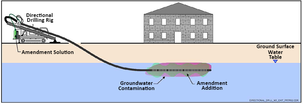
Directional Drilling Blind Installation (Single Ended)
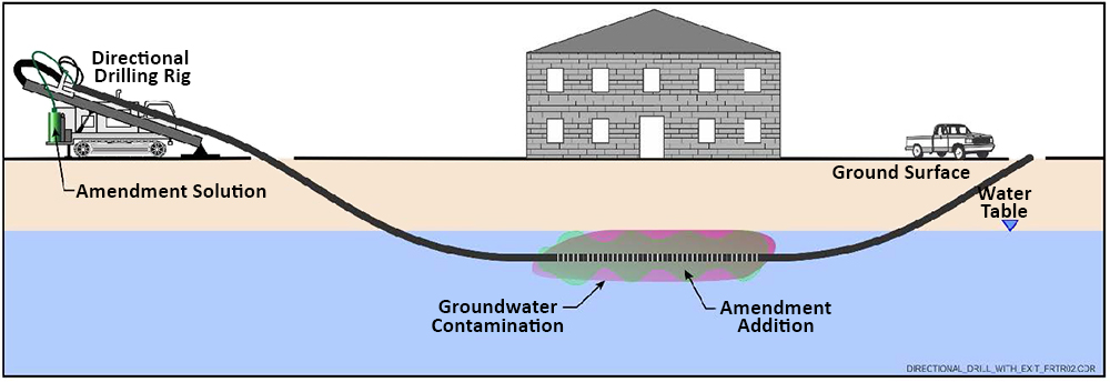
Directional Drilling Continuous Installation (Double Ended)
Introduction
Horizontal drilling techniques are used to position wells at an angle as well as horizontally to reach contaminated portions of the vadose zone and aquifer that are not accessible by direct vertical drilling.
Other Technology Names
Horizontal Wells
Description
Directional drilling is a multi-step drilling technique comprising installation of an initial pilot hole, subsequent reaming of the pilot hole to the diameter required for well installation, and the installation of the well screen and casing materials. Directional drilling typically relies on a mud rotary type technique where mud is used to cool the drill bit and to convey cuttings out of the boring to the surface. Directional drilling can be used to access areas beneath buildings, roads, railways, wetlands or other conditions that limit the use of traditional vertical drilling. Directional drilling techniques can provide more screened area to specific locations within the contaminated zone to enhance groundwater extraction as well as enhance in situ technologies such as bioventing, soil vapor extraction, soil flushing, and technologies that rely on the addition of amendments through wells such as in situ chemical oxidation, reductive dechlorination, and in situ chemical reduction.
Directional drilling is not to be confused with directional boring techniques commonly used to install utility conduits and pipes. Directional boring for utility installation does not require the boring to maintain effective contact with the surrounding aquifer and causes excessive formation damage. Borings advanced by that method cannot be used to install an efficient, usable well. Drilling companies should have documented experience in drilling wells of the type and scale and in similar formations to those being proposed, in the placement of wells and associated filter pack and seal materials, and in the development of horizontal wells having similar screen designs to those proposed. The driller should also be experienced in surveying and documenting the location of the well through its full length.
Isolated contaminated stratigraphic units or thin contaminant plumes within a thicker stratigraphic unit are good candidates for treatment using directional wells since vertical well screens installed parallel with the contaminant zone can achieve greater contact between the well screen and the contaminated zone compared to vertical wells. Directional wells are well-suited for source area treatment. Vertically stacked horizontal wells may be used for installation of permeable reactive barriers or amendment enhanced bio-barriers to prevent plume migration. Multiple horizontal wells may be installed from the same setup location which results in a potentially significant reduction in rig movement and setup costs as well as drill site restoration costs, and limits drilling operation impacts to day to day site activities.
A variety of materials can be used to construct directional wells including polyvinyl chloride, stainless steel, fiber-glass epoxy, and high-density polyethylene. Many pre-packed systems are commercially available. These integrated systems utilize a combination of inner and outer screens and various types of filtration materials, which help to prevent fine-grained silts and sands from clogging the screens. Manufacturers should be consulted for specific design and installation requirements for the type of well that will be used.
Like vertical wells, construction materials for directional wells must be compatible with the design pressure, reagents, and substrates that will be used and the contaminants of concern (COCs) and geochemistry in the aquifer. However, installation of directional wells also must consider tensile and bending stresses. Wire-wrapped well screens are easily damaged. Very straight sections of borehole and a gradual angle of transition from the surface to the directional point below grade facilitate the installation of stiff casing materials (and pre-packed screen systems). Reaming the borehole to several times the pipe diameter also improves the ease in which the well materials can be pulled through the borehole.
The design for directional wells must specify screen length and depth as well as directional and vertical offsets. Most directional wells for environmental applications can range from 100 to 1,000 feet in length; however, lengths of several thousand feet can be accommodated if necessary. Horizontal screens must be designed to ensure complete and efficient sweep of the targeted volume of porous material to provide uniform injection of the fluid if long screens are utilized. Depending on the degree of urban development in the area where the wells are to be installed, determination of a bore path that avoids utilities may be difficult and require significant upfront investigation of utility locations. The wells can be installed "blind", single ended, in which only one end of the well protrudes from the surface or can be installed "continuous", double ended, in which both ends protrude on either side of the screened interval (NAVFAC, 2012). The offset angle, which is the angle formed by the riser and the screen, typically is around 12 degrees. To a large extent, the offset is determined by the type of equipment that is used during installation and the well construction material. Depending on the offset and depth, a substantial length of blank casing may be required on each end of the screen to daylight the well casing at the ground surface. The casing can extend beyond the target treatment zone by a hundred or more feet on either end to account for a gradual rise of the pipe from the target treatment depth to the surface. Setbacks, the distances between the entry point of the casing to the start of the horizontal screen section, typically range from 3 to 5 feet for each foot the screen is placed below grade.
A specialized drill rig is used to install directional wells, which is primarily rated by its pullback force (i.e., the force available to pull the casing and screen through the borehole). The required pullback force is based on the soil type, size of the borehole, length of the borehole, and how straight the borehole was installed. For average soil conditions, the required pullback force for 1,000 feet of well is 40,000 pounds of force (lbf). Most environmental applications require only a small or medium rig, which can generate upwards of 100,000 lbf. However, rigs are available that can generate in excess of 1,000,000 lbf, but these are generally not used in environmental applications (DTD, 2004). The design of appropriate drilling fluids is important to minimize damage to the formation during drilling and to minimize post installation well development requirements to the extent possible.
Development and Implementation Status
The following checklist provides a summary of the development and implementation status of directional wells:
☐At the laboratory/bench scale and shows promise
☐In pilot studies
☒At full scale
☒To remediate an entire site (source and plume)
☐To remediate a source only
☒As part of a technology train
☒As the final remedy at multiple sites
☒To successfully attain cleanup goals in multiple sites
The technology is available through the following vendors:
☐Commercially available nationwide
☒Commercially available through niche vendors1
☐Research organizations and academia
Applicability
Directional well technology is applicable to the complete range of contaminant groups with no target group. It is an alternative well construction method that can be used with virtually any technology where wells are required. Please refer to the Treatment Technology Screening Matrix and the technology profile for the remedy of interest for additional details regarding applicability for a specific technology and group of contaminants.
Cost
Installation of horizontal wells is more expensive than installation of vertical wells; however, fewer wells generally are required in applications. Upfront material and installation costs can be substantial based on the lengths and depths of the wells required. Major cost drivers include:
Upfront Costs
- Type and size of drilling equipment.
- Mobilization/demobilization of drilling equipment. Proximity of drilling rig and tooling.
- Utility clearance at entry / exit pit locations and in the near surface borehole path.
- Drilling method. Depending on desired trueness (horizontal and vertical deviation) of the borehole the steering tool method or cable sonde method for drilling would be needed.
Operation and Maintenance Costs
- Entry / exit pit location(s) and pit size.
- Depth of target treatment zone. Greater depths require a much greater length of blank well casing and greater installation time. In addition, well casing and screen costs will be higher because higher tensile strength material will be needed to handle the skin friction generated during installation.
- Control, containment, and disposal of drilling fluids / cuttings. Due to the length of a well, a substantial volume of drilling fluids / cuttings can be generated.
- Well development. Depending on the application of the directional wells, the wells may need to be periodically developed throughout the life of the well due to biofouling.
Duration
The time required to install directional wells is primarily dependent on well design and the installation equipment used. Installation time increases as the depth and length of the well increase.
The timeframe for operating a directional well is based on the remedial technology that is applied. Please consult specific technology profiles for additional details regarding operational timeframes for a specific remedy.
Implementability Considerations
The following are key considerations associated with applying directional drilling:
- The potential exists for wells to collapse. Conductor casing may be required to help facilitate well installation.
- Specialized equipment is required to install directional wells.
- In shallow applications care must be taken to minimize heaving or fracturing out caused by the drilling fluid.
- Wells can be difficult to position precisely at shallow depths because building columns may prohibit straight installation of wells.
- A tracer that emits a signal may be installed in the drill bit head and used with a global positioning system to help maintain the drill bit head in the desired direction and elevation.
- In some instances, it may be possible to abandon wells by removing the casing and injecting grout into the formation. However, often, collapse of the borehole can occur, hindering introduction of the grout and preventing an adequate seal. If preferential pathways are a concern, an alternative method is to abandon the well in place, injecting grout into the annulus of the well casing.
- Care must be taken to steer the drill head along differing lithology (hard and soft) because the drill head will tend to migrate to the softer material. This would be important if targeting a weathered bedrock interval.
- It is necessary to know how the well will be used to optimize the well design for the remedy that will be applied.
- Care must be taken to ensure that the well screen is installed in the target treatment zone. This is especially critical when the objective is to treat thin layers of contamination.
- Hydra-lock, a condition created when the drilling fluid becomes trapped in the borehole as the reamer is being removed, can occur during back reaming. The resulting pressure must be relieved in order to remove the pipe (NAVFAC, 2012).
- Wells should be developed after installation. Flushing or jetting are effective methods. Swabbing and surging, commonly performed to develop vertical wells, are not very effective. Periodic development may be required during application of the remedy.
- Even distribution of introduced amendments or withdrawal of fluids can be difficult to achieve across the length of the screen.
Resources
Directed Technology Drilling (DTD). Horizontal Environmental Well Design and Installation (2004)
This handbook provides design and installation guidance for directional wells.
Environmental Protection Agency (EPA). Manual: Alternative Methods for Fluid Delivery and Recovery. EPA/625/R-94/003 (1994)
This manual focuses on alternatives to horizontal wells to optimize fluid delivery in the subsurface.
EPA. Analysis of Selected Enhancements for Soil Vapor Extraction, EPA OSWER, EPA/542/R-97/007 (1997)
This document provides an evaluation of selected enhancements, including the use of horizontal wells, for soil vapor extraction (SVE) treatment technologies.
EPA. Abstracts of Remediation Case Studies, Volume 4, EPA 542-R-00-006 (2000)
This volume of abstracts provides a number of case studies, some of which use directional drilling to facilitate site remediation.
Lubrecht, Michael. Horizontal Directional Drilling: A Green and Sustainable Technology for Site Remediation (2012)
Published in Environmental Science and Technology. 46 (5), pp 2484-2489.
This article describes directional drilling principals and the sustainable advantages delivered by directional wells.
NAVFAC. Best Practices for Injection and Distribution of Amendments (2012)
This document provides best practices for introducing amendments for technologies including in situ chemical oxidation, enhanced bioremediation, and in situ chemical reduction using conventional and innovative techniques, including horizontal wells.
Directional drilling is commonly used for installation of utilities (e.g., electrical, natural gas, communications, etc.). However, a few vendors utilize directional drilling in the environmental industry. ↩
Directional drilling is commonly used for installation of utilities (e.g., electrical, natural gas, communications, etc.). However, a few vendors utilize directional drilling in the environmental industry. ↩