
Multi-Phase Extraction
On this page:
- Schematic
- Introduction
- Other Technology Names
- Description
- Development Status
- Applicability
- Cost
- Duration
- Implementability Considerations
- Resources
Schematic
This information may be reproduced without restriction as long as the source attribution is included.
Multi-Phase Extraction 1
Introduction
Multi-phase extraction (MPE) is a technology designed to simultaneously remove any combination of light non-aqueous phase liquid (LNAPL), groundwater, and vapor. Treatment by MPE targets remediation of the vadose (or unsaturated) zone, as well as the difficult to treat capillary/smear zone and shallow saturated zone where a large percentage of residual contaminant mass and LNAPL often accumulates. LNAPL or groundwater recovery can be enhanced by creating a vacuum to induce fluid flow toward recovery wells. The vacuum also draws recharge air from above the ground surface into the vadose zone. This process aerates the soil and can stimulate aerobic biodegradation of petroleum hydrocarbon constituents (bioventing). Volatile organic compounds (VOCs) also will partition into the air and be removed through the extraction wells (soil vapor extraction [SVE]).
Other Technology Names
Bioslurping
Dual-phase extraction
Two-phase extraction
Vacuum-enhanced extraction
Vacuum-enhanced free product recovery
Description
MPE is a technology application that teams vacuum-assisted free product and/or groundwater recovery with bioventing and SVE to simultaneously recover free product (if present) and remediate the vadose and capillary/smear zones and shallow saturated zone. 2 Groundwater, LNAPL, and soil gas typically are recovered simultaneously from wells placed throughout the aerial extent of the treatment area. For vacuum induced LNAPL or groundwater recovery and "slurping" applications, one or more aboveground liquid ring pumps or high-vacuum blowers are used to generate the required vacuum. "Slurping" involves use of a drop tube (stinger) that is placed near the oil-water interface (or bottom of the LNAPL saturated thickness) in each extraction well to focus recovery at the capillary/smear zone fringe and shallow saturated zone where a significant portion of LNAPL and residual hydrocarbon mass tends to accumulate (NFESC, 1996). Drop tube applications involve using high velocity airflow to entrain LNAPL/water droplets at the liquid interface for removal. Product skimmer and/or groundwater pumps are used instead of drop tubes to recover larger LNAPL volumes, or to draw down the water table in more transmissive aquifer units to expose the capillary/smear zone to airflow.
For the drop tube and total fluids pumping approaches, the combined liquid and vapor streams are transported together in a single conveyance line. The combined total fluids stream is passed through an aboveground air-water separator to separate the liquids and vapor, and then through an oil-water separator (if needed) to separate any LNAPL from water. Separate conveyance lines are used for the vapor and LNAPL and/or groundwater if skimmer or groundwater pumps are used for liquids recovery. The vapor and water streams are treated for dissolved phase contaminants, if necessary, prior to final discharge in accordance with local regulations. When low levels of emulsified LNAPL globules are present in the aqueous stream following the aboveground separation steps, a zeolite/clay absorbent media can be used to remove the LNAPL.
MPE systems can be designed and operated to extract soil gas at a lower flow rate to reduce air emissions. In some instances, the air emissions from the MPE system can be kept below air permit discharge levels without treatment. Generally, for less transmissive groundwater units, the "slurping" approach using a drop tube can greatly reduce the volume of groundwater that must be extracted compared to conventional LNAPL skimming or pumping systems, thus significantly reducing groundwater treatment costs. A typical approach would be to operate at higher airflow rates at startup to maximize LNAPL and residual contaminant mass removal and volatilization, and then transition to an alternative approach such as bioventing and/or passive LNAPL recovery technologies using lower flow skimmer pumps, manual bailing, or absorbent socks if a case cannot be made to the agencies to completely discontinue hydrocarbon recovery at that time.
Water and vapor treatment are dictated by regulatory requirements and loadings of contaminants of concern (COCs) in the vapor and aqueous streams. Water treatment can include a number of unit operations such as:
- Air Stripping to treat dissolved phase constituents,
- Liquid-Phase Granular Activated Carbon (GAC) to treat dissolved phase constituents,
- Hydrophobic Clay Media to remove emulsified oil, and
- Chemical Flocculation and Dissolved Air Flotation to remove emulsified oil, residual oil, and metals.
Vapor treatment can include:
- Gas-Phase GAC,
- Thermal or Catalytic Oxidation,
- Internal Combustion Engine (ICE), which can treat concentrations of VOCs greater than 25% of the lower explosive limit without the need for dilution.
During recovery activities, system parameters including blower vacuum(s), any separate liquid phase pump pressures and flowrates, any individual air conveyance line vacuums and airflow rates, and total air emissions are monitored regularly to ensure that the system is operating according to design. The volume of LNAPL and groundwater recovered, total system airflow rate, LNAPL thickness in monitoring wells, and groundwater level elevations are measured periodically. The data are used to optimize operation of the system (i.e., balancing or cycling of wells to optimize LNAPL recovery and vapor phase contaminant removal) and to gauge progress toward achieving remedial goals.
For combined air-water-LNAPL removal using a "slurping" drop tube application, obtaining flow measurements for individual extraction wells is usually not practical. A clear hose is often placed at the outlet of individual wells to visually observe the fluids mixture. Observation of the entrainment of water/LNAPL droplets within airflow denotes typical proper operation, while suction lifting all liquids with no airflow (can occur if the water table rises) denotes the need to raise the drop tube level in a well.
Periodic analysis of COCs in the aqueous and vapor discharge streams is performed to evaluate contaminant mass recovery rates in these media. In addition, depending on the type of treatment employed and discharge requirements, these analyses may be required to comply with regulatory requirements.
Soil gas monitoring points are recommended at multiple depths at several locations for monitoring the concentration of vapor phase contaminants and aerobic respiration parameters for hydrocarbon sites (oxygen, carbon dioxide, methane) in the vadose zone. Respiration tests, which evaluate the change of in situ oxygen and carbon dioxide, can be performed using these points. Results are used to estimate hydrocarbon biodegradation rates and how they change over time (NFESC, 1996).
Process data including LNAPL and groundwater recovery rates along with aquifer transmissivity and LNAPL and groundwater specific gravity can be used to estimate LNAPL transmissivity using the procedures specified in American Society of Testing Materials (ASTM) Method E2856-13. LNAPL transmissivity provides an important line of evidence for evaluating LNAPL mobility and is a useful metric for determining when LNAPL has been recovered to the extent practicable.
Development Status and Availability
The following checklist provides a summary of the development and implementation status of MPE:
☐ At the laboratory/bench scale and shows promise
☐ In pilot studies
☒ At full scale
☐ To remediate an entire site (source and plume)
☒ To remediate a source only
☒ As part of a technology train
☐ As the final remedy at multiple sites
☒ To successfully attain cleanup goals in multiple sites
MPE is available through the following vendors:
☒ Commercially available nationwide
☐ Commercially available through limited vendors because of licensing or specialized equipment
☐ Research organizations and academia
Applicability
|
Contaminant Class Applicability Rating for MPE (Rating codes: Demonstrated Effectiveness, ◐ Limited Effectiveness, No Demonstrated Effectiveness, I/D Insufficient Data, N/A Not Applicable) | ||||||||
|---|---|---|---|---|---|---|---|---|
Nonhalogenated VOC |
Halogenated VOC |
Nonhalogenated SVOC |
Halogenated SVOC |
Fuels |
Inorganics |
Radionuclides |
Munitions |
Emerging Contaminants |
| ● | ● | ◐ | ○ | ● | ○ | ○ | ○ | ♢ |
The combined mechanisms applied in MPE allow effective removal of LNAPL and residual hydrocarbon or VOC contaminant mass within the vadose zone, exposed capillary/smear zone, and shallow saturated zone by a combination of volatilization by SVE and biodegradation by bioventing. MPE is often used to remove LNAPL from source areas. It can be designed to recover a wide range of LNAPLs, ranging from light-end compounds such as gasoline, aviation gasoline (AVGAS), kerosene, and JP-4 jet fuel, to more viscous compounds such as diesel, hydraulic fluid, and JP-5 and JP-8 jet fuels. In addition, it has been used to treat dense non-aqueous phase liquids (DNAPLs) and chlorinated solvents (USACE, 1999). It is possible to treat this wide range of compounds, since MPE can include multiple removal mechanisms (i.e., vacuum-enhanced LNAPL and groundwater recovery, groundwater drawdown to expose the capillary' smear zone, volatilization, and biodegradation). For instance, the bioventing component can be a strong contributor to the total mass removal at sites with a low-volatility fuel such as JP-5, whereas volatilization can be relatively high at sites containing high-volatility fuel such as gasoline or other non-halogenated or halogenated VOCs. For VOCs, groundwater drawdown can be used to expose immobilized residual mass in the capillary/smear zone for removal by SVE or bioventing.
SVE/bioventing can have beneficial impact on dissolved phase groundwater contamination by significantly reducing the source area residual contaminant mass. MPE also can be used to extract source area groundwater for purposes of dewatering or recovery. However, MPE systems should not be designed to specifically target dissolved phase groundwater plumes outside of the source area (e.g., in areas that do not contain LNAPL), since other less costly technologies (e.g., enhanced aerobic bioremediation and air sparging) are available. MPE may be used to dewater thin saturated seams in order to more aggressively remove source area LNAPL and/or residual contaminant mass by SVE/bioventing that would not be effectively treated by saturated zone technologies.
Cost
MPE is an aggressive recovery technology, and its life cycle cost is typically high compared to other less aggressive technologies. The most critical cost factor is associated with treatment of the aqueous and vapor streams. Operating costs can be prohibitive at sites where extensive treatment is required. As with all in situ technologies, application costs vary according to site and contaminants. Major cost drivers include:
Upfront Costs
- Vapor treatment requirements. Initial contaminant influent loading rates for air treatment systems at sites, especially those consisting of significant LNAPL mass requiring aggressive removal, can be high, which could necessitate more costly air treatment technology at startup such as catalytic or thermal oxidation or ICE. Once initial influent loading rates have sufficiently decreased, the air treatment system and/or MPE treatment can be transitioned to a less aggressive and costly technology (e.g., granular activated carbon air treatment and/or bioventing).
- The selection of a fluids removal approach for LNAPL, groundwater, and air is a balance between capital cost, site conditions, and design objectives. A "slurping" drop tube approach for total fluids removal offers a much lower capital cost than individual media pumps, but is viable mostly for lower transmissivity groundwater units and slower LNAPL and groundwater recovery rates. Higher capacity LNAPL skimmer and/or groundwater pumps are needed for larger projected LNAPL recovery volumes and higher aquifer transmissivity applications (also for greater drawdown requirements). For a larger number of extraction wells and longer projected operating timeframes, individual media pumps can also be more cost effective over the project life cycle versus a drop tube system (see "Implementability" section). Skimmer pumps for LNAPL removal are not as susceptible to oil emulsion and fluids separation problems as entrainment of oil droplets in high velocity airflow.
- The number of extraction points/wells required, which is dictated by the areal extent of contaminant mass to be treated and site hydrogeologic conditions, and achievable radius of influence.
- The type, size and quantity of hydraulic pumping (e.g., liquid ring pump) and associated separation equipment (e.g., knockout tanks, oil-water separator).
- Aqueous treatment requirements. Treatment can range from oil-water separation followed by discharge to a sanitary sewer to complex removal of emulsified oils and heavy metals using coagulation/flocculation, dissolved air flotation, hydrophobic clay, and activated carbon.
- Type of recovery manifold (aboveground or subsurface) can have a significant impact on cost.
- Presence of aboveground and below ground structures and utilities.
Operation and Maintenance Costs
- Size of site and availability of remote telemetry system.
- Complexity of fluids recovery system(s) and aqueous and vapor treatment.
- Monitoring requirements after amendment addition.
- Treatment timeframe. Typically, this lasts between 1 and 3 years; however, longer timeframes have been noted.
The list above highlights those cost dependencies specific to MPE and does not consider the dependencies that are general to most in situ remediation technologies. Click here for a general discussion on costing which includes definitions and repetitive costs for remediation technologies. A project-specific cost estimate can be developed using an integrated cost-estimating application such as RACER® or consulting with a subject matter expert.
Duration
MPE systems should be designed to operate for 1 to 3 years. The length of time required for a particular application is dependent on numerous site-specific factors, including:
- The nature of the LNAPL – Weathered viscous LNAPL comprised of long-chained hydrocarbons such as JP-8 is much more difficult to recover than short-chained LNAPLs, such as gasoline, which flows more easily under vacuum and is easily biodegraded and stripped from soil and groundwater.
- Soil properties – LNAPL and/or residual contaminant mass can be more effectively recovered or removed from homogeneous sandy soils compared to sites containing interbedded lenses of silt and clay (i.e., heterogeneous soil lithology).
- LNAPL and soil cleanup goals – A typical requirement is to recover LNAPL "to the maximum extent practicable". Recently, states are considering metrics such as LNAPL transmissivity as one line of evidence for determining when LNAPL recovery may be discontinued (ITRC, 2009) versus the historical 1/8-inch measured LNAPL thickness requirement. A remedial action work plan documenting the metrics by which this will be measured should be agreed upon by site stakeholders prior to implementing the remedy. LNAPL recovery and SVE/bioventing are typically more effective for more permeable vadose zone soil horizons. Treatment of less permeable and heterogeneous lithology may leave untreated pockets of residual contaminant mass, or pose a technical limitation to uniformly achieving soil cleanup goals (a statistically-based soil confirmation approach can be used).
- Aquifer characteristics including permeability and anisotropy.
- The homogeneity of soil/aquifer properties that influence liquid drawdown versus airflow between recovery wells will dictate the number of wells that can be operated concurrently, and the corresponding frequency of cycling changeovers and adjustments to drop tube heights and other operating parameters.
- The achievable rate of LNAPL recovery.
A treatment train approach is commonly used at sites where MPE is employed. As the recovery rate of LNAPL/vapor phase mass removal approach is an asymptotic level, operation of the MPE system should be discontinued and less aggressive technologies such as natural source zone depletion and monitored natural attenuation may be considered.
Implementability Considerations
The following are key implementability considerations associated with applying MPE:
- For "slurping" drop tube applications involving LNAPL recovery or dewatering, heterogeneity of site geology can make it difficult to maintain an operating balance between extraction wells, especially as the number of extraction wells increases. Wells screened in more permeable soil units can lower the fluid levels faster than other wells, which can result in a system operating imbalance (i.e., all airflow occurs from a small number of system wells, while no fluids/air removal occurs at other wells). System imbalances can be addressed either by: periodic adjustments of drop tube levels in individual wells, which can be labor intensive; or implementing a cyclic well operation schedule and grouping similar acting wells together, which would result in increased capital cost for controls and more intensive labor requirements.
- Weathered LNAPLs that contain long-chain hydrocarbons such as diesel, JP-5, and JP-8 can produce substantial oil in water emulsions that are very difficult and costly to separate. These mixtures may require special oil/water separators or treatment methods before the process water can be discharged. These challenges may be reduced by (1) using a dual drop tube or pre-pump separation system (ESTCP, 2003) or (2) placing the air/water separator prior to the liquid ring pump. In some situations, it may be necessary to use chemical flocculation and dissolved air flotation, followed by polishing using GAC or air stripping to remove hydrocarbons from the aqueous stream prior to discharge. Similarly, very high concentrations of hydrocarbons will result in the vapor stream at sites containing very volatile LNAPLs, such as gasoline, which could necessitate more costly air treatment such as thermal oxidation.
- Site geology will influence contaminant mass removal effectiveness:
- Subsurface heterogeneity can interfere with LNAPL flow to the well and uniform distribution of airflow through the treatment zone.
- At sites having low-permeability soils, such as glacial tills, it may be difficult to mobilize the LNAPL and/or create airflow to the extraction well, which would necessitate slower mass removal by SVE and/or bioventing at high operating vacuums. Use of soil permeability enhancement techniques (e.g., fracturing) can also be considered, along with alternative risk-based management strategies.
- Because of its airflow component, MPE will achieve greater hydrocarbon mass removal levels than stand-alone LNAPL recovery techniques, which can leave around 80% of the residual mass immobilized within the soil pore structure once asymptotic removal rates are reached. If insufficient LNAPL mass removal is achieved, measurable LNAPL thicknesses can still intermittently appear and disappear from monitoring wells depending on changing water table levels (i.e., shifting residual saturation levels) and can hinder attaining site closure, even though the LNAPL is immobilized and not susceptible to further migration. A more aggressive MPE approach that involves some level of water table drawdown or dewatering may be performed to achieve more effective reductions of hydrocarbon mass immobilized beneath the water table within the capillary/smear and/or shallow saturated zones. This higher level of hydrocarbon mass removal could be necessary to mitigate long-term mass flux to groundwater (if a risk issue) and attain closure at some sites.
- If implementing a "slurping approach" in less transmissive lithologic units, a drop tube can be placed several feet below the residual hydrocarbon mass to facilitate drawdown of the water table to expose additional residual contaminant mass in the capillary/smear zone, and possibly increasing the radius of influence of an extraction well. However, operating in this manner increases water recovery rate and associated treatment costs.
- As LNAPL and dissolved and vapor phase hydrocarbons are recovered, the need to continue operation of any water and vapor treatment equipment should be re-evaluated as treatment tends to be a high percentage of operation and maintenance costs.
Resources
American Society of Testing Materials (ASTM). Standard Guide for Estimating LNAPL Transmissivity (2013)
This standard describes four methods for calculating LNAPL transmissivity.
Environmental Protection Agency (EPA). Application, Performance, and Costs of Biotreatment Technologies for Contaminated Soils (2002)
(PDF) (125 pp, 2.08 MB)
This document provides a critical review of biological treatment processes including bioslurping for remediation of contaminated soils, including cost and performance demonstrated at full or field scale.
EPA. In Situ and Ex Situ Biodegradation Technologies for Remediation of Contaminated Sites (2006)
(PDF) (22 pp, 921 KB)
This document provides technology descriptions and selection factors for in situ and ex situ biodegradation technologies including MPE.
Environmental Security Technology Certification Program (ESTCP). Application Guide for Bioslurping Principles and Practices of Bioslurping Addendum: Use of Pre-Pump Separation for Improved Bioslurper System Operation (2003)
(PDF) (20 pp, 253 KB)
The purpose of the document is to provide Remedial Project Managers (RPMs) and operators of MPE systems the ability to design and operate pre-pump separation systems to improve the operation of their recovery systems.
The Ground-Water Remediation Technologies Analysis Center (GWRTAC). Bioslurping – Technology Overview Report (1996)
(PDF) (14 pp, 56.3 KB)
This technology summary report provides a brief overview of bioslurping, including an introduction to its general principles, reported applicability and utilization, and cited advantages/disadvantages.
Interstate Technology Regulatory Council (ITRC). Evaluating LNAPL Recovery Technologies for Achieving Project Goals (2009a)
(PDF) (157 pp, 1.98 MB)
Provides a framework to help stakeholders select the best-suited LNAPL remedial technology for an LNAPL site. The document provides guidance for selecting an appropriate technology to specific remedial objectives.
ITRC. Evaluating Natural Source Zone Depletion at Sites with LNAPL (2009b)
(PDF) (76 pp, 1.31 MB)
Describes natural source zone depletion processes and provides best practices for evaluating the rate that natural source zone depletion is occurring.
NAVFAC. Guidance for Optimizing Remedial Action Operation (2012)
(PDF) (94 pp, 2.76 MB)
The document describes optimizing remedial action operations including an overview of free product recovery and discusses common operational problems and optimization strategies.
Naval Facilities Engineering Service Center (NFESC). Bioslurping – Best Practices Manual (1996)
(PDF) (59 pp, 494 KB)
The document presents the general approach for field implementation of bioslurping technology.
NFESC. Application Guide for Bioslurping – Volume I (1998)
(PDF) (17 pp, 222 KB)
An abbreviated version of principles and practices of bioslurping that can help a RPM make preliminary decisions quickly.
NFESC. Application Guide for Bioslurping – Volume II (1998)
(PDF) (166 pp, 1.41 MB)
Detailed description of the bioslurper system, testing procedures, and system design, operation, monitoring and approach for site closure.
NFESC. Bioslurping – Low Volatility Fuels Recovery Trifold (2000)
(PDF) (2 pp, 80.6 KB)
This document teams bioslurping vacuum enhanced free product recovery with bioventing. The Naval Air Station (NAS) Fallon project is highlighted.
NFESC. Use of Pre-pump Separation Technologies to Enhance Cost-Effectiveness of Bioslurper Systems – Long-Term Demonstration (2003)
(PDF) (89 pp, 1.45 MB)
Final report for ESTCP Project #CU-9908, which involved eight short-term demonstrations and one long-term demonstration (at NAS Fallon) to test two pre-pump bioslurper system modifications: modified knockout tank and in-well "dual drop tube" fuel-groundwater separation methods.
United States Army Corps of Engineers (USACE). Multi-Phase Extraction Engineering and Design EM 1110-1-4010 (1999)
(PDF) (286 pp, 6.34 MB)
Design guidance for applying MPE.
USACE. Dual-Phase Extraction (Bioslurping) Engineering and Design – Safety and Health Aspects of HTRW Remediation Technologies, Chapter 9 (2003)
(PDF) (286 pp, 2.55 MB)
This document provides unique hazards associated with dual-phase extraction. Methods for control and control points are also described.
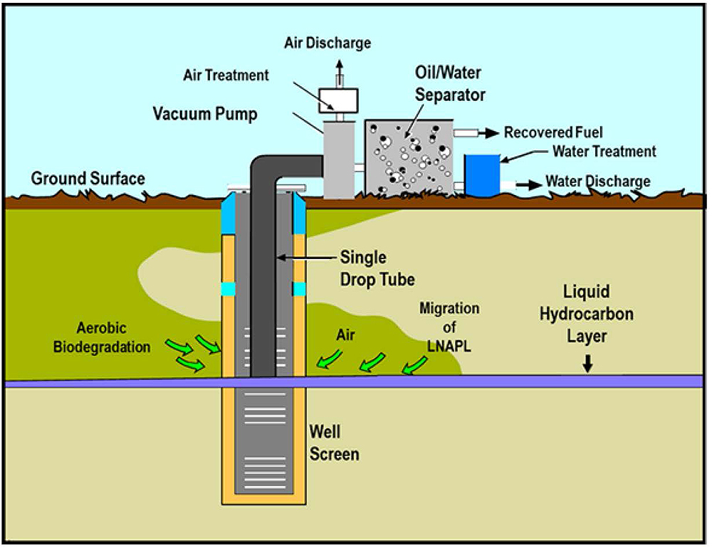
Example of "slurping" MPE configuration involving total fluids removal using a drop tube and vacuum blower. MPE can be any combination of water, non-aqueous phase liquid, and air recovery using wells, blowers, or in-well pumps. ↩
Example of "slurping" MPE configuration involving total fluids removal using a drop tube and vacuum blower. MPE can be any combination of water, non-aqueous phase liquid, and air recovery using wells, blowers, or in-well pumps. ↩
MPE can be used to treat dense non-aqueous phase liquids and chlorinated solvents; however, it is primarily used to treat petroleum hydrocarbons. As such, this profile is primarily focused on the application of MPE to treat LNAPLs and associated petroleum hydrocarbon contamination. ↩
MPE can be used to treat dense non-aqueous phase liquids and chlorinated solvents; however, it is primarily used to treat petroleum hydrocarbons. As such, this profile is primarily focused on the application of MPE to treat LNAPLs and associated petroleum hydrocarbon contamination. ↩