
Biowalls
On this page:
- Schematic
- Introduction
- Other Technology Names
- Description
- Development Status
- Applicability
- Cost
- Duration
- Implementability Considerations
- Resources
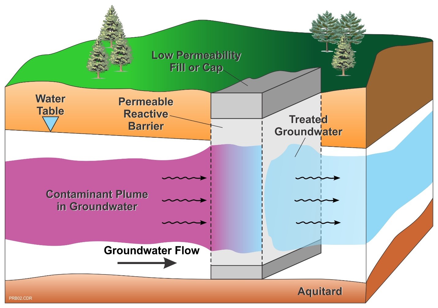
Schematic
This information may be reproduced without restriction as long as the source attribution is included.
Biowall Schematic
Introduction
A biowall is a type of permeable reactive barrier (PRB) that relies on biological processes to treat groundwater in situ. Typically, a biowall involves the installation of media consisting of a carbon source and possibly microorganisms within a trench that is positioned perpendicular to groundwater flow and intersects the contaminant plume. The organic material is used as an energy source by naturally occurring or augmented microorganisms, creating a highly reducing and anaerobic environment in which contaminants of concern (COCs) are degraded as groundwater passes through the wall.
Other Technology Names
Biobarriers
Bioborings
Mulch Wall
Description
Biowalls are a form of bioremediation, in which a permeable barrier is installed across the flow path of a contaminated groundwater plume such that the plume is intercepted and the COCs are biodegraded. Biowalls are an adaptation of the original iron-filled PRB trenches first used in 1995. They require a carbon source and microorganisms to degrade the COCs, and they may be constructed using one or more of the following types of amendments:
- Carbon Source. Common media include solids such as mulch, woodchips, compost, wheat straw, and chitin and liquids including cheese whey, sodium lactate, molasses, emulsified vegetable oils (EVOs), carbohydrates and alcohols (EPA, 2013). A wide-range of proprietary carbon sources also have been developed and are available from vendors.
- Support Material. Sand and gravel can be used to provide a support matrix for the carbon materials to minimize consolidation of the materials and improve permeability to promote groundwater flow through the barrier. These materials generally comprise 40 to 60% of the reactor (AFCEE, 2008).
- Microorganisms. Microorganisms that use carbon as an energy source and create an anaerobic and reducing environment required for degradation of many COCs are ubiquitous in the environment. However, microorganisms that degrade the COCs themselves may not be present in sufficient quantities for biodegradation to proceed. Hence, it may be necessary to augment the biowall with a culture that contains the appropriate dehalorespiring bacteria (e.g., Dehalococcoides, Dehalobacter restrictus to completely degrade trichloroethene [TCE] to ethene).
- Nutrients. The carbon source (e.g., mulch) generally will be high in nutrients including nitrogen and phosphorous. Nonetheless, monitoring should be performed to evaluate analyses prior to installation and at various times during operation to determine the concentrations of nutrients. Additions of nutrients may be needed during construction or as amendments during operation through injection of a liquid.
- Buffers. Biodegradation generates metabolic acids, which may lower the pH of the aquifer. In rare instances, introduction of electron donor can also increase the pH; which can occur due to sulfate- and iron-reduction reactions. The buffering capacity of the reactor material and aquifer should be determined. Limestone can be included as part of the biobarrier during construction to buffer changes in pH. Limestone offers an added advantage in that it also provides support and improves permeability of the barrier. Alternatively, liquid buffer amendments can be added to the reactor during operation if needed to improve its buffering capacity and increase groundwater pH.
- Others. Other types of amendments may be required based on the types of COCs present in groundwater and site-specific conditions and objectives. For instance, it may be desirable to amend the biobarrier with iron and sulfate to enhance biogeochemical transformation processes of chlorinated solvents, by which chlorinated ethenes such as tetrachloroethene (PCE) and TCE are completely dechlorinated to non-toxic products such as acetylene without the production of (toxic) vinyl chloride (VC). However, attempts to establish in situ biogeochemical treatment are oftentimes unsuccessful. Based on difficulties experienced during a recent ESTCP project, it was hypothesized that if introduction of electron donor precedes widespread generation of FeS, the system will never stop generating dichloroethene (DCE) and VC – i.e., once DCE and VC generation become established, it appears that it may not be possible for the FeS-mediated reactions to predominate.
Amendments can be used individually or together, depending on the application and site-specific remedial goals and objectives. For example, mulch could be coated with EVO to form a system to treat multiple contaminants in an anaerobic environment over a long treatment period. Additional information pertaining to bioremediation can be found in the technology profiles for reductive dechlorination, enhanced aerobic remediation, cometabolic remediation, and biogeochemical transformation.
Like other types of PRBs, biowalls may be installed as a continuous reactive barrier, across the entire width and perpendicular to groundwater flow or in a funnel-and-gate configuration, where impermeable walls facilitate groundwater flow through treatment gates. Biowalls can be installed using a wide range of methods. The optimum installation method is site- and application-specific, based on factors such as depth and width of the wall, type and phase (e.g., solid, liquid, gas) of media used, geology and hydrogeology, and existing surface and subsurface infrastructure. Common installation options include:
- One-pass trencher: A one pass trencher is a track mounted, heavy construction vehicle with an extended cutting boom (a linked chain belt with cutting teeth) similar to a chain saw. These are capable of cutting trenches 12 to 36 inches wide and 20 to 50 feet deep. Continuous one pass trenchers simultaneously emplace the biowall media while simultaneously cutting the trench.
- Open trench method: The open trench method typically involves the use of track mounted excavators; i.e., heavy construction vehicles with a bucket or clamshell on the end of a boom, controlled from within a cab on a rotating platform. Excavators have been used for depths of 45 feet and shallower, but they have the potential to trench to a depth of 200 feet below ground surface. Excavators are used to create an open trench (shored if necessary), which is backfilled with the biowall media as a granular material or a slurry. During excavation, the open trench is typically filled with a biopolymer slurry to keep it open.
- Injection of aqueous or gaseous phase reactants through direct injection points or permanent wells:. Aqueous carbon substrates and other amendments (e.g., cultures, pH buffers, and nutrients) in a carrier fluid are injected under pressure, with the goal of achieving the most continuous reactive zone possible. Gases also may be introduced under pressure through points or wells. This method typically results in a less continuous reactive zone than trenching or borings, but borings but can be used at some sites where other methods are not practical. Additional guidance to inject and distribute aqueous amendments can be found here.
To determine the optimal installation method, the following factors must be considered:
- Depth and width of the biowall
- Biowall media to be installed
- Detailed site geology and hydrogeology
- Identification of preferential flow paths
- Depth to which the aquifer is contaminated
- Existing surface and subsurface infrastructure
The location of a biowall relative to the contaminant plume at a site depends on the treatment objectives and how the biowall is incorporated with other technologies in a "treatment train." Biowalls can be used to reduce the mass flux from a source zone by positioning the biowall at the immediate downgradient edge of the source zone. They can alternatively be used mid-plume to reduce dissolved concentrations in a key location. Key performance factors of biowalls are:
- Establish and maintain the hydraulic conditions necessary for effective treatment, including sufficient residence time for contaminated groundwater within the media and effective routing of the contaminated groundwater through the media without deflection or bypass.
- Treat the target contaminant(s) to meet the remedial action objective at the specified distance downgradient of the biowalls.
Development Status and Availability
The following checklist provides a summary of the development and implementation status of biowalls:
☐ At the laboratory/bench scale and shows promise
☐ In pilot studies
☒ At full scale
☒ To remediate an entire site (source and plume)
☐ To remediate a source only
☒ As part of a technology train
☐ As the final remedy at multiple sites
☐ To successfully attain cleanup goals in multiple sites
Biowalls are available through the following vendors:
☒ Commercially available nationwide
☐ Commercially available through limited vendors because of licensing or specialized equipment
☐ Research organizations and academia
Applicability
|
Contaminant Class Applicability Rating for Biowalls (Rating codes: Demonstrated Effectiveness, ◐ Limited Effectiveness, No Demonstrated Effectiveness I/D Insufficient Data, N/A Not Applicable) |
||||||||
|---|---|---|---|---|---|---|---|---|
Nonhalogenated VOC |
Halogenated VOC |
Nonhalogenated SVOC |
Halogenated SVOC |
Fuels |
Inorganics |
Radionuclides |
Munitions |
Emerging Contaminants |
| ● | ● | ● | ● | ● | ◐ | ◐ | ● | ◐ |
The contaminant groups targeted by biological barriers consist of aerobically and anaerobically biodegradable compounds such as halogenated and nonhalogenated volatile organic compounds (VOCs), semi-volatile organic compounds (SVOCs), and polychlorinated biphenyls (PCBs), energetics (munitions constituents) such as trinitrotoluene (TNT) and Royal Demolition Explosive (RDX), uranium, and dissolved inorganics that can be reduced and form a precipitate (e.g., chromium VI to III). If groundwater at a site is naturally aerobic and the biowall creates anaerobic conditions, an aerobic zone will be present at some distance from the biowall, which can 1) promote biodegradation of other constituents, such as VC, which might be created and slow to degrade in the anaerobic zone but will more rapidly degrade in the aerobic portion of the site, and 2) reprecipitate metals that are mobilized under biowall anaerobic conditions, e.g. arsenic, manganese, and iron. Biological barriers can also treat petroleum hydrocarbon constituents.
Cost
Cost drivers for biowalls include the type and quantity of media required, and the emplacement methods needed. Major cost drivers include:
Upfront Capital Costs
- Area and depth of contaminants requiring treatment, which impact the length and depth of the biowall and, therefore, the quantity of media required and the emplacement methods that can be selected.
- Expected groundwater flow rate and mass flux of contaminants through the biowall, which determine the necessary thickness and, therefore, quantity of biowall media required, as well as impacting the expected longevity of the media.
- Nature of the contaminants and degradation pathways, which determines the bioreactor biobarrier media type that should be used, and impacts the expected longevity of the media. Mulch, gravel, and sand are relatively inexpensive; however, cost for implementation of amendments such as pH buffering reagents, bioaugmentation cultures and other specialized carbon substrates can be greater.
- Need to perform mathematical groundwater modeling to demonstrate effectiveness and optimize the design.
- Biowall construction requires the use of heavy equipment to install the system. Installation activities include monitoring well installation; trenching and/or drilling; reactive media emplacement; and transportation of materials. Drill rigs, continuous trenchers, backhoes, delivery trucks, and other large equipment are usually required. Fracturing and injections require pumping and/or pressurized injection, often using substantial amounts of water and/or gases.
- Costs to dispose of investigation-derived waste (IDW) during drilling and/or excavation activities.
- Number and depth of injection points. At some sites, biowalls may be installed by injecting amendments through a series of injection points or wells. An adequate design for well monitoring network including the number, spacing, and well pairs (upgradient and downgradient) should be planned. Depending on the considerations, the number and depth of the points/wells installed can have a significant impact on cost.
Operation and Maintenance Costs
- Labor for operation, maintenance, and monitoring.
- Longevity of media, which is dependent on the types of media used and COCs, contaminant concentrations, and site characteristics. Re-application of amendments (carbon source, buffers, etc.) may be required to maintain bioreactor performance.
- Remedial goals and performance criteria.
- Need for periodic hydraulic conductivity testing to assess whether groundwater is still flowing through the biowall.
- Number of monitoring wells.
- Potential biological and/or chemical fouling and related treatment. This applies to the biowall itself, wells, and injection points for replenishing electron
The list above highlights those cost dependencies specific to biowalls and does not consider the dependencies that are general to most in situ remediation technologies. Click here for a general discussion on costing which includes definitions and repetitive costs for remediation technologies. A project-specific cost estimate can be obtained using an integrated cost-estimating application such as RACER® or consulting with a subject matter expert.
Duration
Biowalls are passive in nature and typically require longer times to achieve cleanup goals than do other more aggressive remedial technologies. If biowalls are employed at a site where an aggressive and compatible technology is used to treat a source area, the duration to operate the biowall may be shorter. At some sites, biowalls are designed as part of a plume containment system, the operation of which can last for decades. Also, in many cases, biowalls are used with monitored natural attenuation, in which case the duration in which the biowall is operated will increase. The longevity of biowalls is dependent on many factors, including the following conditions:
- Groundwater quality and waterborne inhibitors that poison biowall catalysis or microflora
- Groundwater flowrate and mass flux of contaminants
- Native and anthropogenic electron acceptor demand impacting the media use rate
- Iron and sulfate availability and usage (determines biogeochemical transformation process rates)
- Initial quantity and reactivity of the media used in the biowall
There have been documented cases of sawdust-filled biowalls successfully treating nitrate plumes for 7 to 15 years with little decrease in performance (ITRC PRB-5). Injectable substrates derived from solid carbon are intended to perform for 5 to 10 years before replenishment is needed. Slow release substrates such as EVO and hydrogen-releasing compounds have lifetimes of 1.5 to 5 years. There have also been cases where permeable reactive barriers became clogged, and were no longer functional. If a biowall becomes severely clogged, water will be forced to flow around, or under the biowall; and the biowall may have to be abandoned.
Implementability Considerations
The following are key considerations for the application of biowalls:
- Very high contaminant concentrations may be toxic to microorganisms.
- Sulfide toxicity produced from sulfate-reducing conditions may play a role in limiting microbial activity.
- Depletion of the carbon source over time will occur, which can contribute to decreased performance. However, the biowall can be amended with liquid carbon substrates to prolong its longevity.
- Biofouling or formation of precipitates (especially when removing metals) can reduce biowall permeability.
- Toxic byproducts (e.g., VC) can be created and accumulate because of reductive dechlorination stall. These byproducts can travel downgradient outside of the biowall. In addition, changes in geochemical conditions can mobilize naturally-occurring minerals that may be toxic (e.g., arsenic) or result in exceedances of secondary groundwater quality standards (e.g., pH, total dissolved solids, odors). It is necessary to ensure that any byproducts will attenuate naturally and will not pose risk to any downgradient receptors.
- There is also the possibility of vapor intrusion impacts to nearby buildings due to potential generation of methane, hydrogen sulfide, and/or VC.
- Proximity of the plume to site boundaries or receptors.
- Depth and width of the contaminant plume. Improper design and implementation could result in a plume that could flow under or around biobarriers.
- Formation of metabolic acids during degradation of contaminants can lower the pH within and immediately downgradient of the bioreactor. Limestone can be included in the biobarrier during construction to buffer changes in pH. Alternatively, liquid buffer amendments can be added during operation if needed.
- Cost of treatment media.
- Will not treat downgradient residual plumes. Secondary treatment may be necessary to address residual contamination downgradient of a biowall.
- Hydraulic failure due to poor design will limit effectiveness of the treatment.
- Deed restrictions for groundwater use may be required if the upgradient source area is not remediated or until all of the contaminants are treated by the biowall.
- Nearby dynamic loading (future pile driving, dewatering, excavation) can compromise the structure of the biowall.
Resources
AFCEE. Technical Protocol for Enhanced Anaerobic Bioremediation Using Permeable Mulch Biowalls and Bioreactors (2008) (PDF) (302 pp, 5.56 MB)
This protocol recognizes potential biowall/bioreactor sites and assists in appropriate design and application of the remedy.
EPA. Introduction to In Situ Bioremediation of Groundwater (2013) (PDF) (86 pp, 2.23 MB)
This document provides an overview of in situ bioremediation and serves as a reference for designers and practitioners.
ESTCP. Addendum to Principles and Practices Manual - Loading Rates and Impacts of Substrate Delivery for Enhanced Anaerobic Bioremediation. ESTCP Project ER-200627 (2010) (PDF) (39 pp, 473 KB)
Enhanced in situ anaerobic bioremediation involves the delivery of organic substrates into the subsurface to stimulate anaerobic degradation of contaminants in groundwater. Effective application of the technology depends primarily on the delivery of appropriate levels of organic substrate in the subsurface and the development of optimal geochemical and oxidation-reduction (redox) conditions for anaerobic degradation processes to occur. Determining an appropriate substrate loading rate and an effective distribution method for the various substrate types commonly applied is a critical design and operational objective
ITRC. PRB Technical Update (July 2011) (PDF) (234 pp, 7.58 MB)
Most recent update to four previous ITRC guidance documents on PRBs.
NAVFAC. Permeable Reactive Barrier Cost and Performance Report (2012) (PDF) (85 pp, 3.40 MB)
This report provides an evaluation of cost and performance conducted for three full-scale PRBs representing a range of installation technologies, reactive media, and targeted contaminants. Injection media used ranged from zero valent iron (ZVI) that stimulates abiotic transformation of chlorinated solvents, to organic materials (e.g., mulch; vegetable oil) that treat perchlorate and enhance reductive dechlorination of chlorinated solvents.
NAVFAC. Permeable Mulch Biowalls Technology Transfer Tool
This tool covers the treatment of contaminated groundwater using mulch biowalls and reviews the mechanism by which the contaminants are degraded. Considerations when designing and installing a biowall are explained. Two case studies are presented where mulch biowalls were installed.
SERDP-ESTCP. Permeable Mulch Biowalls (January 2007)
This online tool provides training regarding design considerations for permeable mulch biowalls, as well as case studies at Navy and Air Force sites.
SERDP-ESTCP. Development of Permeable Reactive Barriers (PRB) Using Edible Oils (July 2008) (PDF) (159 pp, 1.26 MB)
Reports on a laboratory and pilot-scale study of the transport of emulsified oils in aquifers and the effects on contaminant biodegradation.